Schematic diagram of the brake equipment placement on TEM31 diesel locomotive
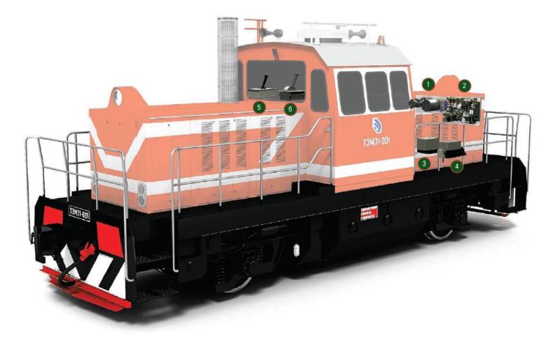
1 Air distributor unit 010.10
2 Electro-pneumatic devices block 130.10
3 Electro-pneumatic auto-stop valve, with remote control 151D-1
4 Locomotive Auxiliary Brake Crane, with 224D Remote Control
5 Auxiliary brake crane controller for 224D.100 locomotive
6 Driver crane controller 130.52