Schematic diagram of the brake equipment placement on the passenger wagon
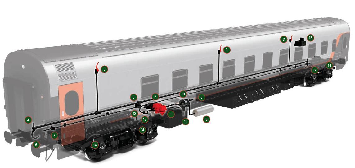
1 Electric air distributor 305
2 Air distributor 242-1-01
3 Stop-crane 138-1
4 End crane
5 Tee 373P
6 Connecting sleeve 369A
7 Terminal box 317-8
8 Auto-regulator РРРП-675М
9 Spare tank
10 Brake Cylinder
11 Exhaust valve 131
12 Disconnecting crane
13 Terminal box 316-8
14 Thermal sensor 005
15 Grease box overheating control block BKNB 004