
Schematic diagram of the brake equipment placement on the metro head wagon
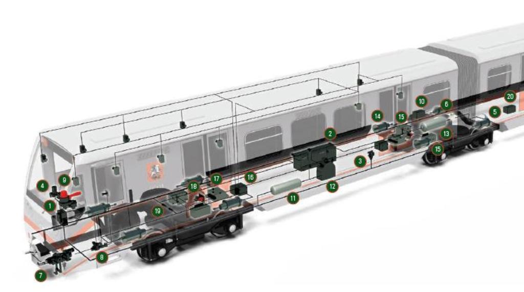
1 Control crane 013A
2 Electro-pneumatic device 248
3 Reducer 348-2
4 Electro-pneumatic valve 177
5 Disconnecting crane 154
6 Reverse crane 161
7 Shear valve 363-3M
8 Valve 144
9 Pressure alarm 115
10 Parking brake control block BUST 192
11 Main tank
12 Compressor
13 Spare tank
14 Brake Cylinder
15 Body position adjuster 003M
16 Switching valve 108
17 Limiting valve 109
18 High-speed valve 398
19 Discharge valve 131
20 Valve dumping, three-position КСТ 182
Friction brake control unit 076Brake equipment block 077